Power transformers and distribution transformers are essential components of our electrical grid, yet many engineers and project managers struggle to distinguish between them. This confusion can lead to costly specification errors and project delays.
A power transformer typically operates at voltages above 66kV and handles bulk power transmission, while a distribution transformer operates below 34.5kV and delivers electricity to end users. However, these categories often overlap, and specifications matter more than labels.
 vs distribution transformers")
Understanding the differences between transformer types is crucial for proper system design and implementation. Let me break down the key distinctions and explain why focusing on specifications rather than terminology will save you headaches in your renewable energy projects.
What is the Difference Between Power Transformer and Distribution Transformer?
Many engineers face challenges when selecting the right transformer type for their projects. This confusion can lead to incompatible equipment purchases and costly redesigns.
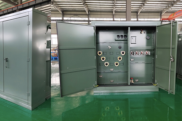
Power transformers typically handle voltages above 66kV with capacities from tens to hundreds of MVA, operating at transmission substations. Distribution transformers manage voltages below 34.5kV with smaller capacities (up to a few MVA), delivering electricity directly to residential and commercial users.

When we examine power and distribution transformers more closely, several key technical differences emerge. Power transformers are designed for high-voltage transmission networks, often connecting generating stations to the grid. They typically operate at full load continuously with minimal load variation. Their efficiency is optimized for peak loads, and they're built to withstand significant system disturbances.
Distribution transformers, however, serve a different purpose. They're the final voltage transformation stage before electricity reaches consumers. These transformers experience variable loading throughout the day and must be designed for optimal efficiency at lower loads (50-70% of capacity). They typically have higher impedance values compared to power transformers of similar ratings, which helps limit fault currents.
| Feature | Power Transformer | Distribution Transformer |
|---|---|---|
| Voltage Rating | Typically >66kV | Typically <34.5kV |
| Capacity | 10 MVA to 500+ MVA | 5 kVA to 5 MVA |
| Load Pattern | Constant, near full capacity | Variable throughout day |
| Efficiency Design Point | Optimized for full load | Optimized for 50-70% load |
| Core Loss vs. Copper Loss | Lower core loss prioritized | Balance between losses |
| Location | Generation plants, transmission substations | Near end consumers |
| Cooling Systems | OFAF, ONAF, or ODAF for larger units | ONAN for most applications |
What is the Difference Between a Current Transformer and a Distribution Transformer?
I've seen many renewable energy developers confuse these transformer types, leading to serious measurement errors and safety issues. The functions are fundamentally different.
Current transformers (CTs) are instrument transformers that measure electrical current by producing a proportional secondary current for metering and protection. Distribution transformers change voltage levels to deliver usable power to end consumers. CTs monitor system performance while distribution transformers enable power delivery.

Current transformers and distribution transformers serve entirely different purposes within electrical systems. A current transformer is fundamentally a measuring instrument, not a power delivery device. CTs have a primary winding consisting of very few turns (sometimes just a single conductor passing through a toroidal core) and a secondary winding with many turns. This configuration allows them to step down current at a precise ratio while increasing voltage.
The most critical difference lies in their application. Distribution transformers transfer power efficiently between voltage levels, while CTs provide accurate current measurements for metering, relay protection, and control systems. Additionally, CTs must never have their secondary circuits open-circuited when current flows through the primary, as this creates dangerous high voltages that can damage equipment and pose serious safety hazards to personnel.
| Aspect | Current Transformer (CT) | Distribution Transformer |
|---|---|---|
| Primary Function | Measurement/instrumentation | Power delivery |
| Turns Ratio | Few primary turns, many secondary | Based on voltage conversion needs |
| Primary Circuit | Connected in series with load | Connected in parallel with load |
| Secondary Load | Meters, relays, instruments (low burden) | Consumer electrical loads |
| Safety Concern | Must never operate with open secondary | Can operate at no-load |
| Typical Size | Compact, often ring-type | Larger oil-filled or dry-type cabinets |
| Rating Basis | Current ratio (e.g., 200:5A) | Power capacity (kVA) and voltage |
| Installation | Inside switchgear or on busbar/cable | On poles or in dedicated enclosures |
How Can You Tell if a Transformer is a Power or Distribution Transformer?
I've watched clients struggle with transformer identification, often relying solely on physical appearance. This approach frequently leads to incorrect applications and operational inefficiencies.
To identify transformer type, examine the nameplate for voltage ratings (power >66kV, distribution <34.5kV), capacity (power: tens to hundreds of MVA; distribution: typically <5 MVA), and impedance values. Also check cooling codes—ONAN is common for distribution while ONAF/OFAF systems suggest power transformers.

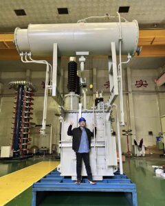
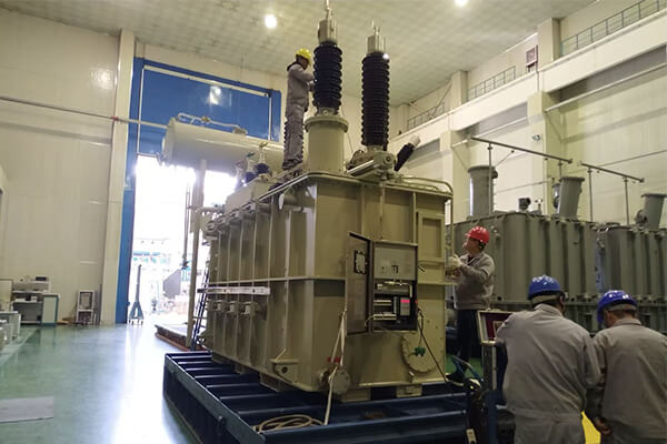
Identifying whether you're dealing with a power or distribution transformer requires looking beyond just the name assigned to it. The physical characteristics often provide immediate clues. Power transformers tend to be significantly larger due to their higher voltage insulation requirements and cooling needs. They typically feature more elaborate bushings, especially on the high-voltage side, with longer creepage distances to prevent flashover.
Cooling systems represent another key differentiator. Power transformers often employ forced-oil and forced-air cooling (OFAF) or directed-oil forced-air cooling (ODAF) for their higher capacity needs. Distribution transformers generally use simpler oil-natural air-natural (ONAN) cooling, though larger units may incorporate fans. The impedance percentage also differs significantly—power transformers typically have lower impedance values (around 5-10%) compared to distribution transformers (normally 4-8%).
| Identification Feature | Power Transformer | Distribution Transformer |
|---|---|---|
| Bushings | Larger, more elaborate with higher clearances | Smaller, simpler design |
| Cooling System | Often ONAF, OFAF, or ODAF with radiators and fans | Typically ONAN, sometimes ONAF for larger units |
| Size-to-Capacity Ratio | Larger physical size relative to MVA rating | More compact relative to MVA rating |
| Tap Changer | Often on-load tap changers (OLTC) | Usually off-load tap changers only |
| Conservator Tank | Almost always present | May be absent in smaller units |
| Monitoring Equipment | Extensive (temperature, gas, oil level) | Basic or minimal |
| Lightning Arresters | Usually external, separate installation | Often integrated or mounted on tank |
| Foundation Requirements | Substantial, engineered foundations | Simpler mounting (pole, pad, vault) |
What is the Difference Between a Substation Transformer and a Distribution Transformer?
I've encountered many projects where these transformer types were improperly specified, causing significant integration problems and additional costs. Understanding their distinct roles prevents these issues.
Substation transformers are larger units (typically >10 MVA) that reduce transmission voltages (>69kV) to sub-transmission levels (usually 26-69kV) for regional distribution. Distribution transformers are smaller units (<5 MVA) that further reduce voltage to utilization levels (typically 120-600V) for direct consumer use.

Substation transformers occupy an intermediate position in the power delivery chain, bridging the gap between high-voltage transmission and local distribution networks. It's important to note that substation transformers are not a separate technical category – they can be either power transformers or distribution transformers depending on their specifications. The term "substation transformer" simply indicates the location and function within the grid rather than specific technical characteristics.
This overlap highlights why focusing on transformer names or categories can be misleading. A substation might contain large power transformers stepping down transmission voltages to sub-transmission levels, or it might house distribution transformers delivering power directly to local circuits. What matters most is the actual specifications – voltage ratings, capacity, impedance values, and cooling systems – rather than the terminology used to describe them. Engineers should always evaluate the technical requirements of their specific application rather than relying on potentially ambiguous category names.
| Feature | Substation Transformer | Distribution Transformer |
|---|---|---|
| Category Definition | Functional location (in substation) rather than technical type | Technical specification based on voltage/capacity |
| Technical Classification | Can be either power or distribution transformers | Defined by specific voltage/capacity parameters |
| Location | Within substation perimeter | Often near end users (pole, pad, vault) |
| Protection Scheme | Complex (differential, restricted earth fault, etc.) | Simple (fuses, reclosers) |
| Redundancy | Often N-1 or N-2 redundancy design | Limited or no redundancy |
| Monitoring | SCADA integration, online monitoring | Usually limited or manual inspection |
| Responsibility | Utility or transmission company | Utility or sometimes end customer |
| Standards/Testing | Rigorous testing based on actual specifications | Testing appropriate to voltage class and application |
Conclusion
Understanding transformer types comes down to examining specifications rather than just labels. Look at voltage ratings, capacity, and installation context to make the right choice for your project. At Voltori Energy, we engineer custom transformers for your unique renewable energy applications, ensuring optimal performance for Canadian solar and wind projects.