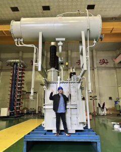
I've seen it happen too many times - a seemingly healthy transformer suddenly fails, disrupting an entire renewable energy system. The culprit? An inter-turn short circuit that could have been prevented with proper knowledge and maintenance.
An inter-turn short circuit in a transformer occurs when insulation between adjacent turns in a winding deteriorates, creating an unwanted current path. This causes localized overheating, reduced efficiency, and can lead to complete transformer failure if not detected early and addressed properly.
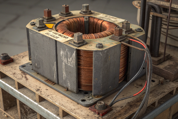
Working in the transformer industry for years, I've learned that understanding these failures isn't just technical knowledge—it's essential business insight. As renewable energy continues to grow across Canada, the reliability of transformers becomes even more critical to maintaining consistent power delivery. Let me share what I've learned about these problematic conditions and how we can prevent them.
What is the inter turn fault in a transformer?
Every time I inspect a failed transformer, I'm reminded how one small insulation breakdown between turns can cascade into catastrophic failure, causing extensive downtime and replacement costs.
An inter-turn fault in a transformer is a type of winding failure where current bypasses its normal path to flow between adjacent turns in the same coil due to insulation breakdown. This creates circulating currents that generate excessive heat in a localized area, eventually leading to more severe insulation damage and transformer failure.
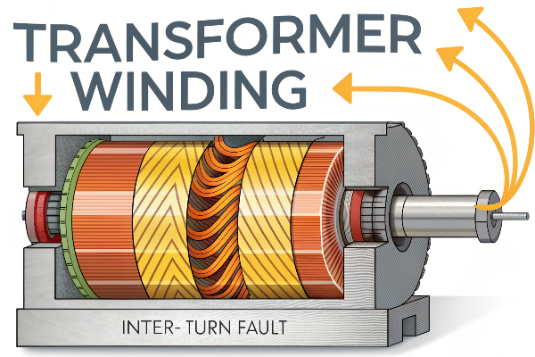
Inter-turn faults are particularly dangerous because they often begin small and go unnoticed. In my experience working with custom-engineered transformers for renewable energy applications, I've seen how these faults develop gradually. The fault typically starts with a small insulation weakness that allows a minimal current to flow between turns. This creates a "hot spot" in the winding where temperatures rise above normal operating levels.
| Inter-Turn Fault Progression | Effects | Detection Methods |
|---|---|---|
| Initial insulation weakness | Small electrical discharges, minimal heating | Dissolved Gas Analysis (DGA) |
| Carbonization of insulation | Increased conductivity, more current flow | Frequency Response Analysis (FRA) |
| Expanded fault area | Higher temperatures, surrounding insulation damage | Power factor testing |
| Advanced stage | Major current deviation, significant heating | Differential protection relays |
| Critical stage | Catastrophic winding failure | Often too late for prevention |
What makes these faults challenging to detect is their subtle initial impact. Standard protection devices like overcurrent relays might not trip because the fault current is relatively small compared to the transformer's rated current. But don't be fooled by this quietness—the localized heating steadily degrades surrounding insulation, expanding the fault area and creating a snowball effect.
What causes a short circuit in a transformer?
I've investigated dozens of transformer failures and found that behind almost every short circuit lies a combination of aging, environmental stressors, and sometimes, maintenance oversights that could have been prevented.
Short circuits in transformers are primarily caused by insulation breakdown due to aging, overheating, moisture ingress, mechanical stress, manufacturing defects, voltage surges, or contamination. These factors compromise the dielectric strength of insulating materials, creating paths for current to flow where it shouldn't.
 transformer insulation damage](https://voltoritransformer.com/wp-content/uploads/2025/09/image-3-close-up-image-of-transformer-insulation-m.png)
Digging deeper into transformer short circuit causes has been a necessary part of my role in designing resilient supply chains for the renewable energy sector. When a transformer fails at a solar farm or wind power plant, the consequences extend far beyond the immediate replacement costs. There's the lost energy production, potential grid instability, and in some cases, contractual penalties for energy not delivered.
| Cause | Mechanism | Prevalence in Renewable Energy Applications |
|---|---|---|
| Insulation Aging | Thermal degradation following Arrhenius relationship | High in solar applications due to daily thermal cycling |
| Overheating | Exceeding temperature limits, accelerated aging | Common during peak generation periods |
| Moisture Ingress | Reduced dielectric strength, increased conductivity | High in coastal wind farms |
| Mechanical Stress | Displacement of windings, insulation abrasion | Elevated in transportable or mobile substations |
| Manufacturing Defects | Voids in insulation, improper clearances | Low with proper quality control |
| Voltage Surges | Insulation breakdown from transient overvoltages | Common in areas with frequent lightning activity |
| Contamination | Conductive paths across insulating surfaces | High in dusty environments or industrial areas |
From my perspective managing supply chains for transformer manufacturing, thermal stress from overloading is another common culprit I've encountered. When transformers operate above their rated capacity for extended periods, especially during peak renewable energy generation or high demand periods, insulation weakens more rapidly. This is why we emphasize proper sizing in our custom engineering process, with particular attention to the unique load profiles of renewable energy applications.
What is the condition for short circuit current?
I remember analyzing a wind farm transformer failure where the short circuit current was so intense it warped the copper windings beyond recognition—a stark reminder of the forces at play when impedance drops unexpectedly.
Short circuit current occurs when the impedance in a transformer circuit drops significantly below normal levels, allowing current to flow at values much higher than rated conditions. This happens when there's a direct path between phases or between a phase and ground due to insulation failure, with current limited only by the transformer's leakage reactance.
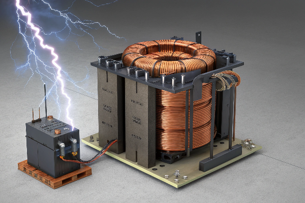
The physics behind short circuit currents in transformers is something I've had to understand deeply to ensure our supply chain delivers components that can withstand these extreme events. In normal operation, transformer impedance—composed of winding resistance and leakage reactance—limits current flow to designed values. However, when insulation fails and creates a direct path with much lower impedance, the current can increase dramatically, sometimes reaching 20-25 times the rated current in severe cases.
| Short Circuit Type | Typical Magnitude | Primary Effects | Secondary Effects |
|---|---|---|---|
| Three-Phase Fault | 20-25× rated current | Maximum thermal and mechanical stress | Symmetrical forces on windings |
| Phase-to-Phase Fault | 15-20× rated current | High thermal stress, unbalanced forces | Winding displacement |
| Phase-to-Ground Fault | Depends on grounding | Tank heating, core saturation | Potential zero sequence currents |
| Inter-Turn Fault | Initially low, increases over time | Localized heating | Progressive insulation deterioration |
This massive current surge creates two immediate problems I've seen firsthand in failed units. First, the thermal effect: I²R losses generate intense heat that can melt conductor insulation within seconds. Second, the electromagnetic forces between conductors increase with the square of the current, creating mechanical stresses that can physically deform or displace windings.
From my supply chain perspective, this understanding drives several critical specifications for our transformers. We carefully select conductor materials and sizes with adequate thermal capacity. Mechanical bracing within the transformer must be robust enough to withstand electromagnetic forces during faults. Insulation systems need appropriate dielectric strength with margins for aging and stress.
How do you protect a transformer against incipient faults?
After witnessing a solar farm lose production for weeks due to a transformer failure that began as a tiny inter-turn fault, I became passionate about implementing comprehensive protection strategies across our entire product line.
Protecting transformers against incipient faults requires a multi-layered approach: implementing online monitoring systems like DGA (Dissolved Gas Analysis) and partial discharge detection; using thermal imaging; installing specialized protective relays; conducting regular oil testing; and employing preventive maintenance schedules with frequency response analysis and insulation resistance tests.
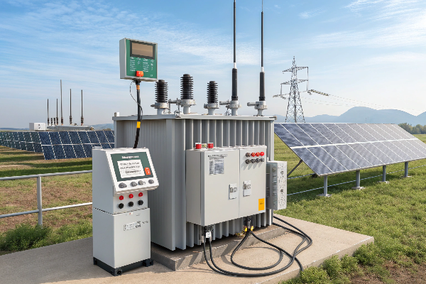
In my years overseeing transformer supply chains for renewable energy projects, I've developed a comprehensive approach to protecting against these hidden threats. The strategy I recommend combines sophisticated technology with rigorous maintenance practices, creating multiple layers of defense against incipient faults.
| Protection Method | What It Detects | Implementation | Effectiveness |
|---|---|---|---|
| Dissolved Gas Analysis (DGA) | Thermal faults, partial discharges, arcing | Online monitoring or periodic sampling | Excellent for early detection of internal faults |
| Partial Discharge Monitoring | Insulation deterioration | Acoustic sensors, UHF sensors | Very good for tracking insulation aging |
| Thermal Imaging | External hot spots, cooling issues | Periodic inspection | Good for connection problems |
| Buchholz Relay | Gas accumulation, oil surges | Installed between tank and conservator | Excellent for detecting internal faults |
| Differential Protection | Current imbalances | Current transformers, relay systems | Very effective for major faults |
| Pressure Relief Devices | Dangerous pressure buildup | Installed on tank | Critical for safety |
| Frequency Response Analysis | Winding deformation, movement | Periodic testing | Excellent for mechanical issues |
| Oil Quality Testing | Moisture, acidity, interfacial tension | Regular sampling | Good indicator of insulation health |
| Load Management Systems | Prevent thermal overloading | Online monitoring, controls | Preventive rather than detective |
Dissolved Gas Analysis (DGA) has proven to be our most valuable early warning system. By monitoring gas concentrations in transformer oil—particularly hydrogen, methane, ethylene, and acetylene—we can identify specific fault types before they become catastrophic. I've implemented continuous online DGA monitoring for critical transformers in large-scale solar and wind installations, allowing for real-time trend analysis and immediate alerts when gas levels indicate developing problems.
I've also found that proper loading management is crucial for long-term transformer health. For renewable energy applications, this means carefully accounting for the variable nature of generation sources. Solar farm transformers, for instance, experience daily thermal cycling that differs significantly from traditional baseload applications, requiring special consideration in both design and operation.
Conclusion
Understanding inter-turn short circuits has proven vital to ensuring transformer reliability in renewable energy projects. These hidden faults can quickly escalate from minor issues to catastrophic failures if left undetected.
At Voltori Energy, we engineer our transformers with superior insulation systems and comprehensive monitoring, delivering the reliability your renewable energy project demands.
